|
|
|
Categories
|
|
Information
|
|
Featured Product
|
|
|
 |
|
|
There are currently no product reviews.
 ;
Original well scanned manual. Got the job done. Microwave problem found & corrected. For $5 and a new magnitron from ebay, it was a cheap and good the first shot fix. Electrical schematics allowed me to mage sure every thing else was ok before cutting and order for parts. Hard to live without.
;
I was very skeptical of this website, I have never downloaded manuals before. I put it on the AMEX and payed through Paypal to ensure protection. I got the manual exactly as described and now I can replace the filter capacitor for this amp. Great Price, others selling for 12.99 or more and this is the same manual. I will search out this website for other manuals. Thank you
;
Manual was reasonably easy to follow. I am not an engineer or know much about electronics but with the manuals help I was able to figure out the problem, identify the part required for the repair. Replacement part cost around $30. Whilst replacing the part I was telling myself, "this aint gonna work cos it seems far too easy". Took about 15 minutes to do and my plasma TV works a treat. Would never have been able to do this without the service manual.
;
It is OK, this manual help me to repair my dynacord
 ;
Good manual. Even it is an old printed manual, it is well scanned and complete, with all drawings, schematics and parts list. Very good return for the cost.
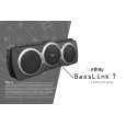
BassLink T
DISASSEMBLY PROCEDURE FOR BASSLINK T (ACCESS TO AMPLIFER, DRIVERS)
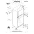
1) On a protected work surface, stand the unit up so the back panel is facing you. 2) Remove the (12) Phillips screws holding the black heatsink to the enclosure. Do not remove the heatsink at this time. 3) Remove the (36) Phillips screws holding the back panel to the main enclosure. Note in the area of the heatsink, two screws are shorter, machine screws. 4) Carefully separate the back panel from the main enclosure; try not to damage the O-ring that may be adhered to both sides of the enclosure, preventing its separation. Note the LED wires from the heatsink area routed to the amplifier; unplug the 2 lead connection at female connector M2 on the amplifier. Set the heatsink and LED w/ wires aside. 5) Unplug the woofer wires from the terminals. 6) Completely separate the two enclosure halves. SERVICING THE INPUT/PREAMP SECTION 7) Remove the (8) Phillips screws holding the cover plate to the enclosure. 8) With a wood chisel or similar tool, carefully pry the plastic cover away from the cup, working around the perimeter, until the cover is detached. If the cover is damaged during this procedure, order part# 309-ABS-05002. REASSEMBLY 9) If the cover to input/preamp section was detached, apply a bead of silicon sealer or similar adhesive around the perimeter of the cover, in the sealing groove. Without this adhesive, there may be an air leak which would affect performance. Press the cover into place. 10) Attach the woofer wires. 11) Before the enclosure can come together, connecting the heatsink/LED wire presents a challenge if not correctly done. The LED wire must thread through the enclosure, the small hole in the aluminum heatsink plate, and back into the M2 connector on the amplifier. The position in which this is best achieved is with Basslink T laying flat side down on a surface, woofer side up. Partially bring the enclosure halves together, and work through the remaining gap near the heatsink end. See illustration. 12) Make sure the O-ring around the perimeter of the enclosure is intact and in place. Make sure the two shorter machine screws are used in the back panel, in the area near the heatsink. 13) Replace all enclosure and heatsink screws.
8
|
|
|
> |
|